Programming
These instructions demonstrate how to program and debug the MSP430 on cuplTag.
Equipment
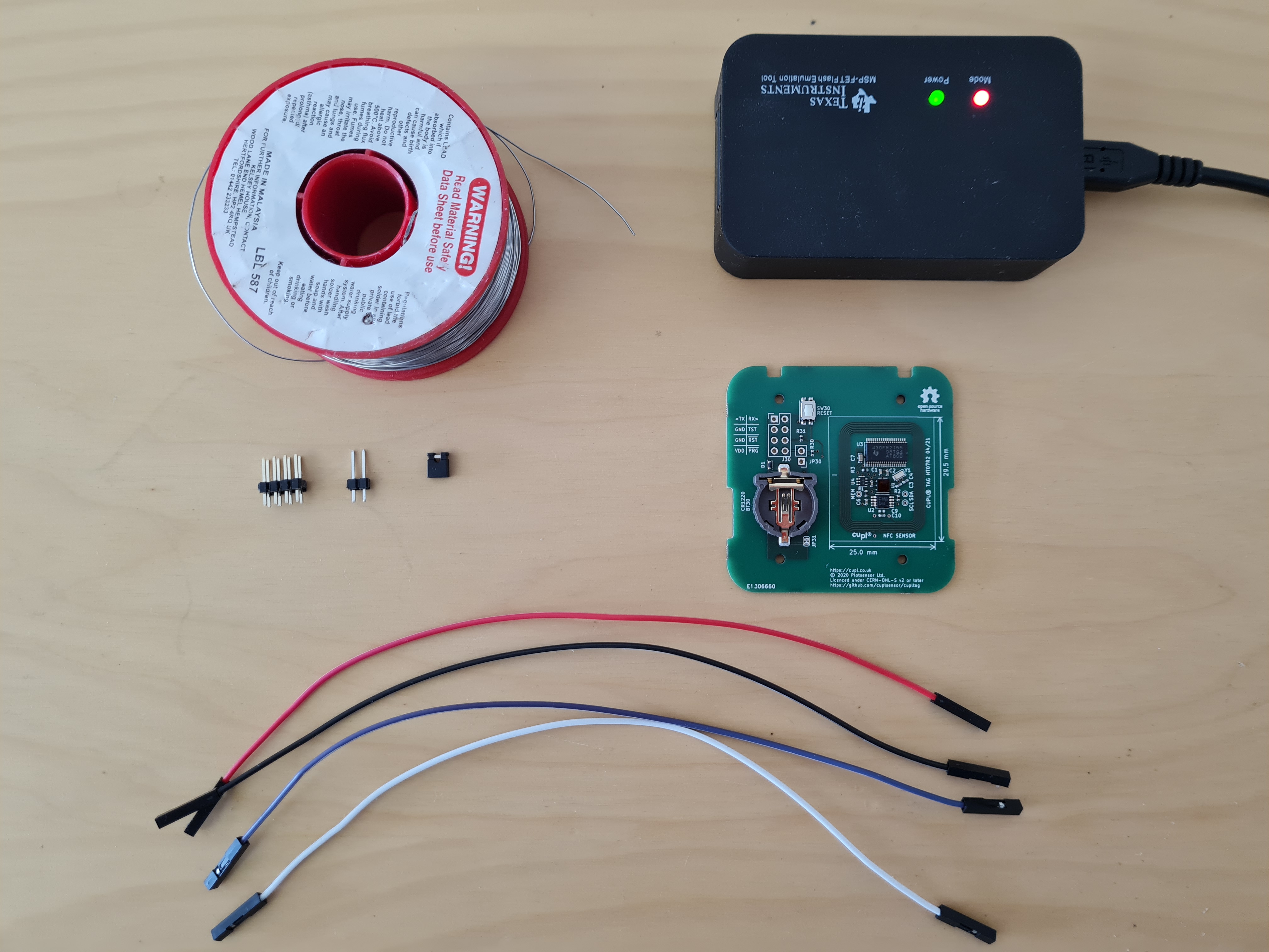
You will need:
An MSP-FET with a USB cable.
A PC running Code Composer Studio.
4 coloured jumper wires.
A 2x4 way 2.54mm pitch pin header.
A 1x2 way 2.54mm pitch pin header.
A 2 way jumper.
Solder.
A cuplTag PCBA (HT07), unscrewed from the enclosure, with no battery inserted.
Populate the Headers
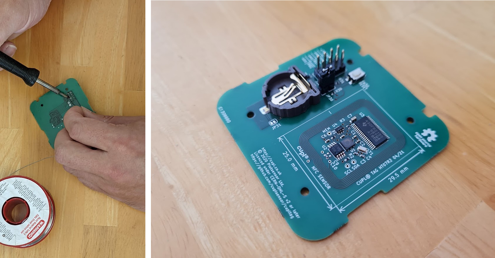
First, solder the pin headers onto J30 and JP30 of HT07. Use the jumper to short JP30.
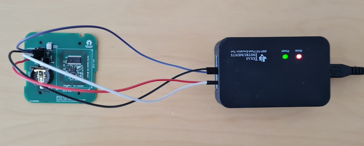
Make Connections
In the diagram below we will make connection J2 instead of J1, because the HT07 has no battery inserted.
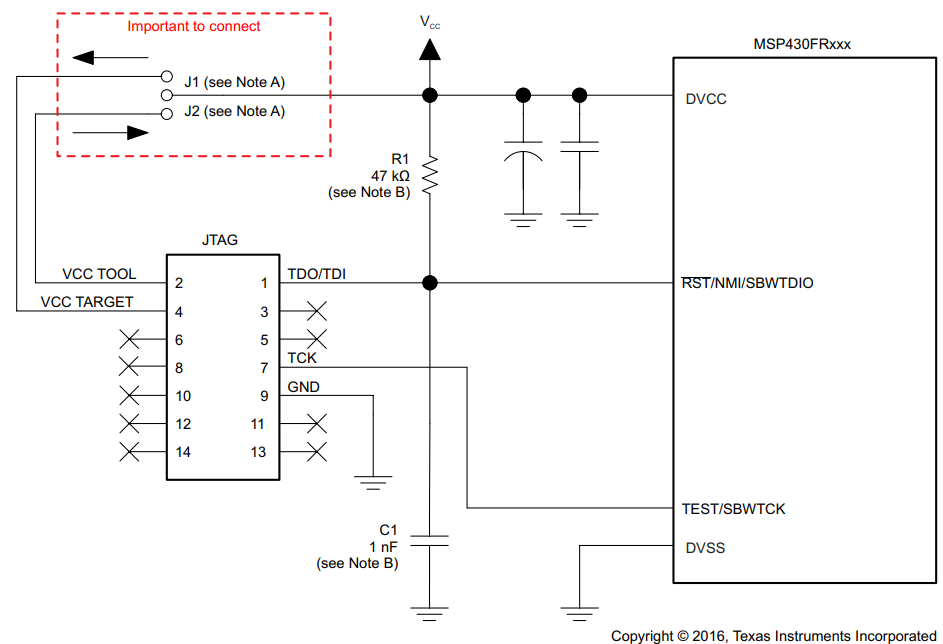
Spy-Bi-Wire is used to progra . Connect it to the MSP-FET.
Name |
Colour |
MSP-FET name |
MSP-FET pin |
HT07 J30 pin |
HT07 J30 name |
+3V3 |
Red |
VCC_TOOL |
2 |
7 |
VDD |
GND |
Black |
GND |
9 |
3 |
GND |
SBWTDIO |
White |
TDO/TDI |
1 |
6 |
nRST |
SBWTCK |
Purple |
TCK |
7 |
4 |
TST |
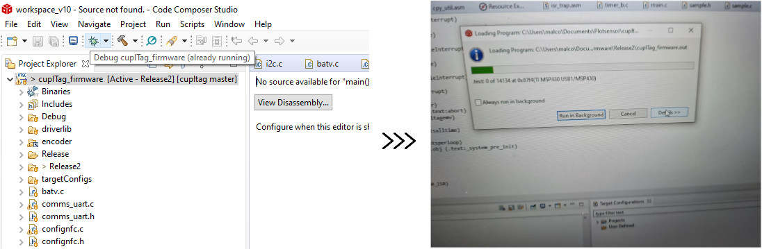
Program in CCS
Connect the MSP-FET to a PC with a USB cable.
Open the Code Composer Studio cuplTag project created earlier <GettingStarted>.
Click on the Debug button. Wait for programming to complete.
Test
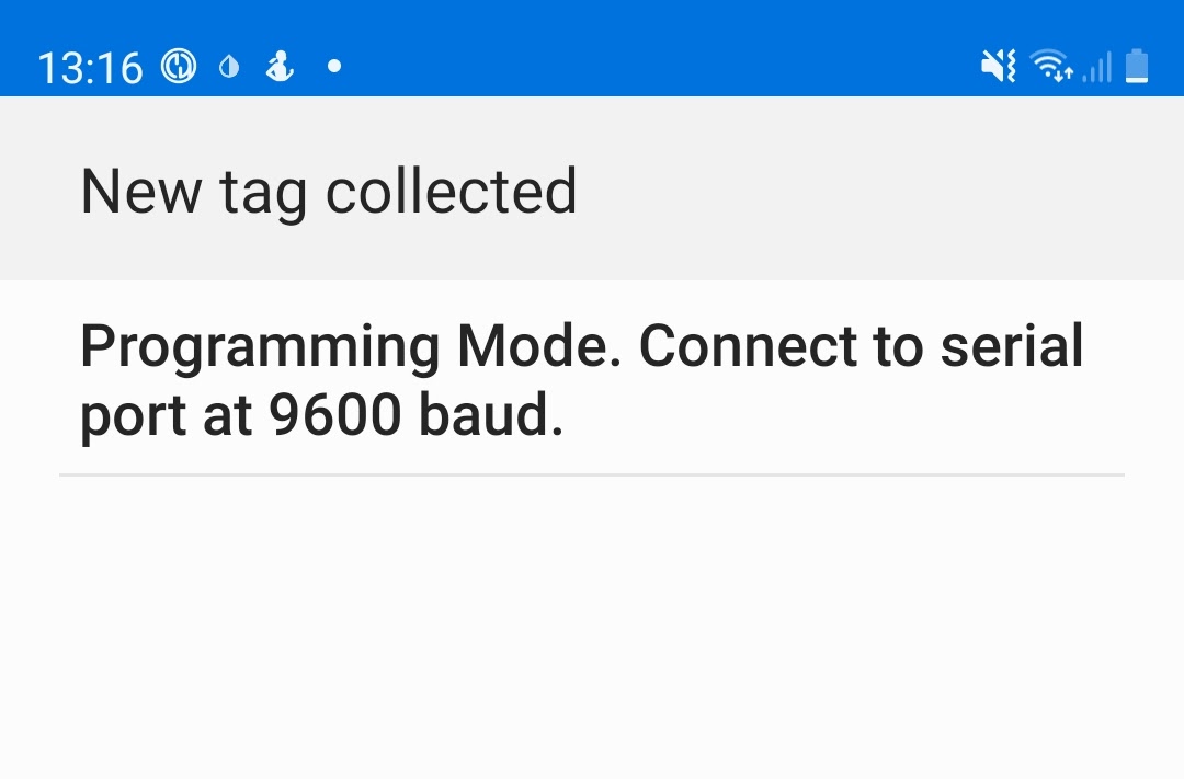
Test the program has loaded correctly by scanning HT07 with your phone.
If JP30 is shorted, the MSP430 will boot into programming mode: The serial port is enabled and a status string is written to an NDEF text record on the tag.